Excavations
The initial aim of the excavations was to locate the line and nature of any remains of the railway line from the Swing Bridge and the siding to the canal. It was not known how much, if any of the metal rails remained in situ, and whether they were fixed to wooden, stone or concrete sleepers.
In addition it was hoped to note any
- abandonment deposits, showing what happened to the site when the railway was no longer in use, and
- in use deposits showing the materials carried on the railway such as flint, coal, colour minerals, etc. .
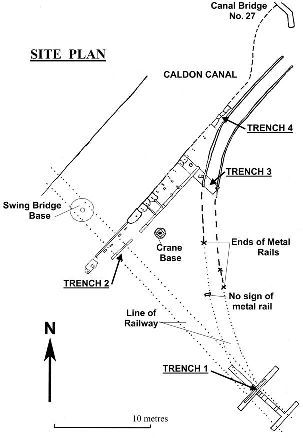
Trench 1 was dug where it was thought the intersection of the main railway line from the Swing Bridge with the branch siding should be, Figure 36.
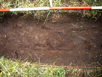
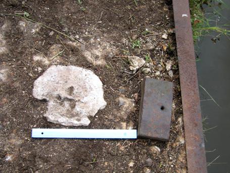
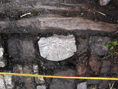
The remains of a wooden sleeper was located about 150mm below the surface, Figure 37, but there was no sign of any metal rails, although a couple of metal bolts were found.
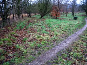
A narrow extension trench to Trench 1 was then excavated to the south-east, away from the canal and Swing Bridge as shown in Figure 36. A series of further wooden sleepers were located, although some had disappeared completely so they were not always at regular intervals. No remains of sleeper or rails were found in the wider trench at the end of this extension, although the line of the railway had been visible in winter from the south-east corner of John Emery Land, Figure 38.
Similarly no sleeper or rail remains were located when a narrow extension trench was excavated to the north-west, towards the canal and Swing Bridge as shown in Figure 36.
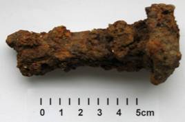
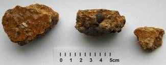
The finds located in this area confirmed the use of the railway, with a rail bolt, Figure 39; the expected raw materials for the Mill: White and Pink Feldspar, Flint, Cornish Stone, and Coal; and some Clinker and Glazed Coarse Pottery, possibly from a Saggar, Figure 40. See Appendix 2 for pictures of the other finds which were more generally distributed around the site.
Trench 2 was opened to try and confirm the line of the railway from the Swing Bridge, Figures 41 and 42, it was later extended to either side of the Swing Bridge.
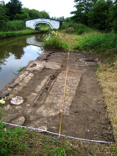
The Canal Bank where the Swing Bridge “landed” was marked by a long metal angle iron bar, presumably reflecting the width of the bridge. Moving away from the canal, the area was made up of hardcore, with an area of concrete at the north eastern end.
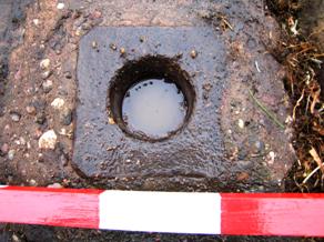
There were three metal pads to support the bridge when it was opened for rail traffic. Each pad had a small hole, possibly for greasing, Figures 42 & 43.
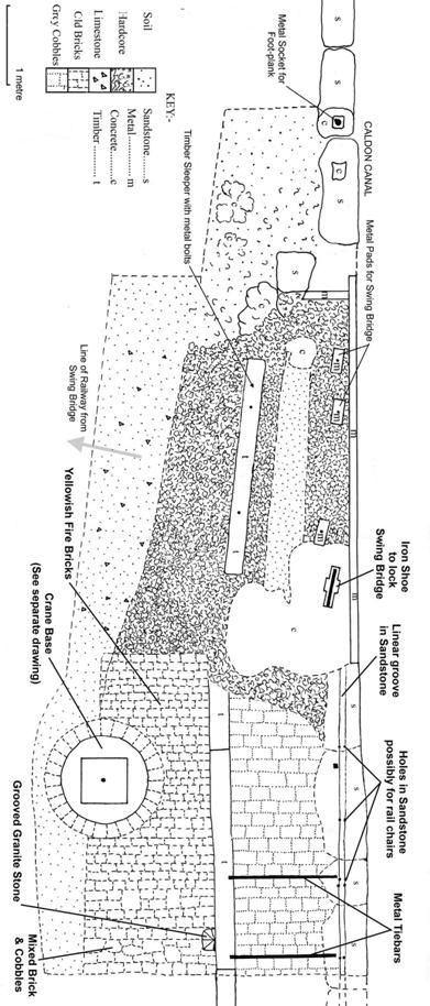
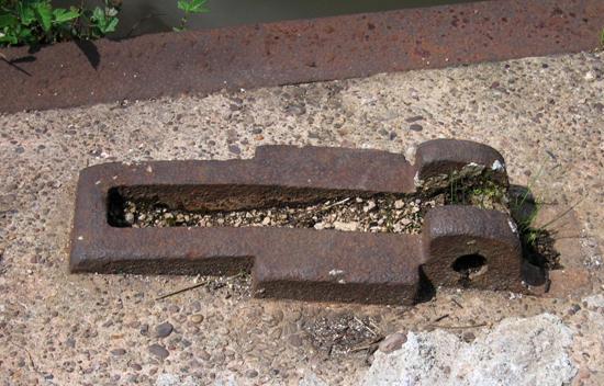
In addition there was an iron shoe arrangement to lock the bridge in this position, Figures 42 & 44.
Moving further away from the canal edge there was a timber sleeper, set at a slight angle from the canal edge, with an area of soil following the line of the canal edge and the sleeper, between the sleeper and the canal edge, Figure 42. The timber sleeper had a couple of metal fixing pins 4ft4ins or 1.32m apart.
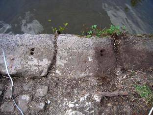
Sandstone blocks edging the canal were present for a short distance to the south west of the bridge landing, and all the way to Canal Bridge on the other side. The hardcore away from the canal edge petered out in the area to the south west of the bridge landing, being replaced by soil. However, there were some interesting features on the two sandstone blocks nearest the bridge landing, Figures 42 and 45.
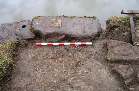
The socket would appear to be the pivot point for the plank bridge to reach the Swing Bridge in the middle of the canal so that the Swing Bridge could be opened for rail traffic, Figure 46. The concrete patch in Figure 45 could also be associated with this plank bridge. The handrail for this bridge was shown in Figure 31 but there is no evidence of any fixing holes for this in the sandstone edge blocks beyond the blocks shown in Figure 45, see Figure 42.
On the other side of the Swing Bridge landing, the canalside area has a number of interesting features. The sandstone blocks along the canal edge show a linear groove, parallel to the canal, with holes at regular intervals, usually in pairs, Figures 42 and 47. These could have been used for metal chairs to hold a rail in the groove.
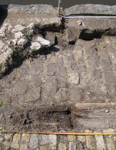
Inside the sandstone edging the area was paved with grey cobbles until it reached a line of timber sleepers laid parallel to the canal edge, and attached to the sandstone edging by a series of metal tiebars, Figures 42 and 48.
 Sandstone edging
Groove with marker in one of the holes
End of missing tiebar
Grey Cobbles apparently going under concrete of Swing Bridge landing
Timber Sleeper
Paving of reused yellowish fire-bricks
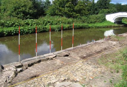
The grey cobbles appeared to predate at least the later phases of the Swing Bridge Landing. The distance between the groove and the sleepers was 1.4m or 4ft 8ins. When ranging rods were put in the holes in the sandstone edging blocks it could be seen that they were at regular intervals, spaced about 1m or 3ft apart, Figure 49.
The yellowish firebricks were used to pave the area up to the crane base which was surrounded with a ring of these bricks. A detailed drawing of the crane base is shown in Figure 50.
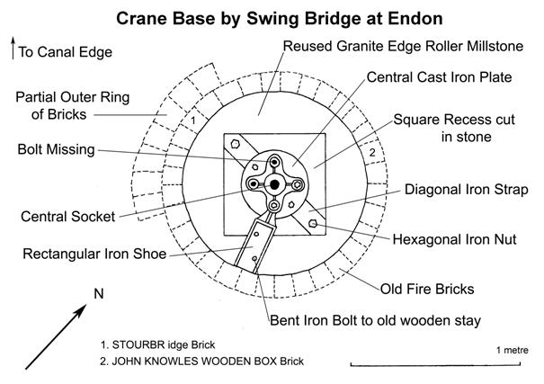
A couple of the reused firebricks had names on them, STOURBRIDGE and JOHN KNOWLES WOODEN BOX. Stourbridge fire-clay has a world-wide reputation, and is important in the manufacture of fire-bricks. The bricks were shipped by Severn Trows to Gloucester , and no doubt up the Staffordshire & Worcestershire Canal to the Trent & Mersey Canal and hence to Endon. John Knowles was based at Mount Pleasant Works, Wooden Box, (changed to Woodville-7th Nov. 1845) in Burton on Trent, and was producing a wide range of products including Fire bricks, Stone Gullies, Blue Coping Stones and Terracotta Vases in 1902 . A large number of fire bricks would have been needed for the Fritting Furnaces at the Phoenix Works, and these would have had to be renewed at regular intervals.
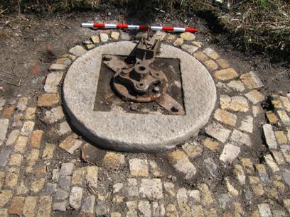
The crane base is also shown in a photograph in Figure 51. It appeared to have been made from a reused granite edge runner, which had been carefully cut away to give a square hole to accommodate the diagonal metal straps holding the metal socket for the crane. A metal shoe for a timber appeared to have been originally able to rotate about the crane base. It was positioned furthest away from the canal to act as some kind of counter support for the crane when lifting.
The only picture showing anything like a crane on the site is Figure 30, which appears to show a very simple type of crane.
Although there is oral evidence for its use for lifting stone out of canal boats, and also into railway trucks, the base seems to be rather a long way back from the canal edge and the railway from the Swing Bridge.
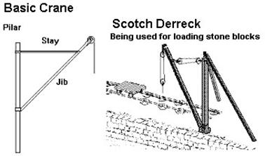
Some simple crane types are shown in Figure 52 .
The basic crane with pilar, stay and jib is not unlike the one shown in Figure 30, which appears to have some kind of hand crank on the main upright.
It is interesting that the Scotch Derreck Crane has an associated rail track.
Beyond the Crane Base the yellow brick pavement becomes an increasing mix of reused bricks and cobbles, including a strange grooved granite stone shown in Figures 42 and 53.
Timber sleeper
Grooved GraniteStone (centre)
Grey Cobble (right)
Red Brick (right)
Yellow Brick (left)
Tape & Datum Line